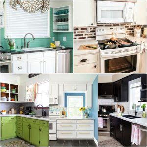
- DIY Kitchens Planner: 30 Ideas You Must Know (2024)
- 24 DIY Home Painting Tips You Must Know (2024)
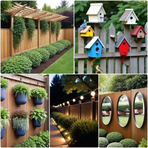
- 30 Fence Decorating Ideas to Spruce Up Your Outdoor
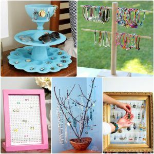
- 25 Homemade DIY Jewelry Display Ideas
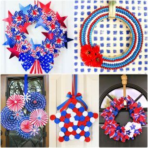
- 25 Easy DIY 4th of July Wreath Ideas
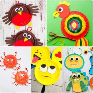
- 30 Paper Plate Crafts for Kids {Preschoolers & Toddlers}
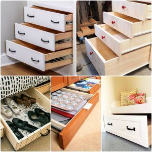
- 25 Easy DIY Drawers: How To Make a Drawer
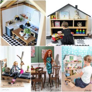
- 25 DIY Dollhouse Furniture Ideas Out Of Household Items
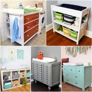
- 25 Free DIY Changing Table Plans Anyone Can Build
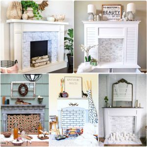
- 25 DIY Faux Fireplace Ideas: Build Your Own Fake Fireplace
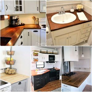
- DIY Wood Countertops: 25 Ideas to Build Your Own
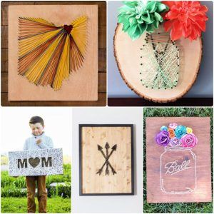
- 30 Easy DIY String Art Ideas and Crafts
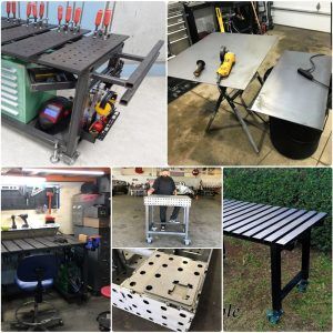
- 20 Homemade DIY Welding Table Plans and Ideas
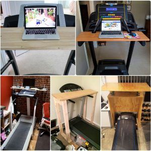
- 20 Homemade DIY Treadmill Desk Ideas
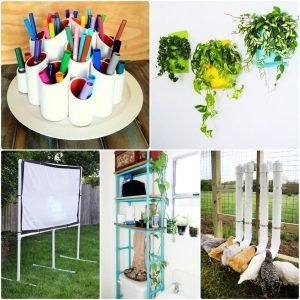
- 30 Easy DIY PVC Pipe Projects and Crafts
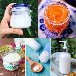
- 25 Homemade Lotion Recipes: How To Make Lotion
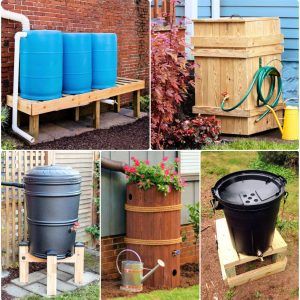
- 25 Cheap DIY Rain Barrel Ideas to Make and Save
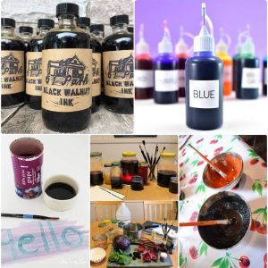
- How to Make Ink: 20 Ways to Homemade Ink
- 30 DIY Keychain Ideas: Make Your Own Keychains
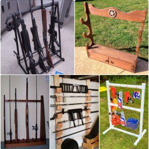
- 20 Homemade DIY Gun Rack Plans
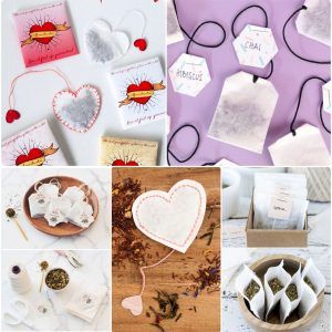
- 20 Homemade DIY Tea Bags to Make Your Own
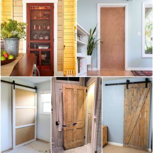
- 15 Ways to Hang a Door and Install a Door Frame
- 30 Free Friendship Bracelet Patterns: DIY Your Bracelets
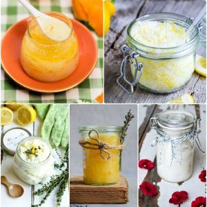
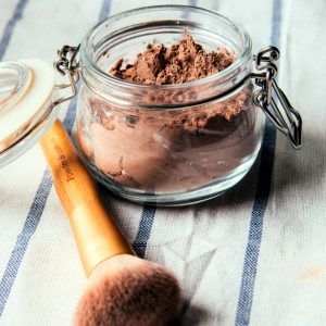
- 25 Homemade Hand Scrub Recipes You Can Easily DIY
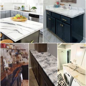
- 25 Easy DIY Epoxy Countertops: How To Step by Step
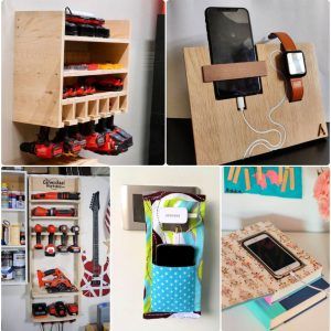
- 30 DIY Charging Station Ideas for Multiple Devices
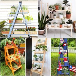
- 20 Beautiful DIY Ladder Plant Stand Ideas
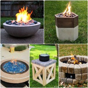
- 20 DIY Gas Fire Pit Ideas: How to Build Your Own
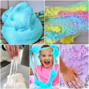
- 20 DIY Cloud Slime Recipes To Make at Home
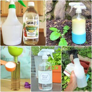
- 15 Homemade Weed Killer Recipes You Can DIY
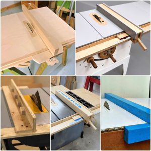
- 20 Free DIY Table Saw Fence Plans You Can Make
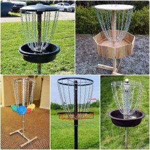
- 20 Homemade DIY Disc Golf Basket Ideas
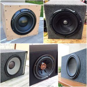
- 20 Free DIY Subwoofer Box Plans to Build Your Own
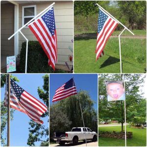
- 20 Homemade DIY Flagpole Plans and Ideas
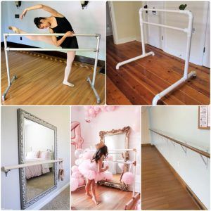
- 20 DIY Ballet Barre Ideas: Build Your Own Barre
- 25 Homemade DIY Dry Shampoo Recipes
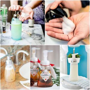
- 30 Homemade DIY Foaming Hand Soap Recipes
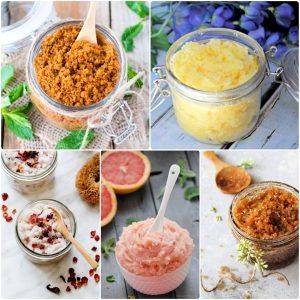
- 50 Homemade DIY Body Scrub Recipes
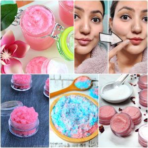
- 35 Homemade DIY Lip Scrub Recipes to Make at Home
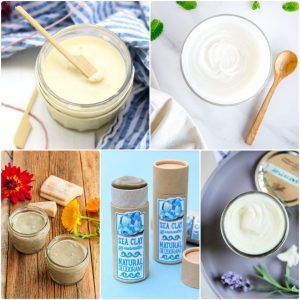
- 30 Homemade Deodorant Recipes You Can DIY
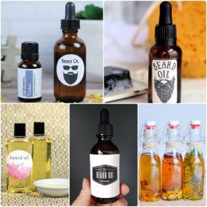
- 25 Homemade DIY Beard Oil Recipes to Make
- 15 DIY Professional Bath Bomb Recipe To Make
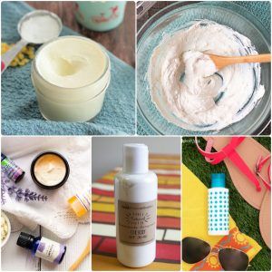
- 20 DIY Homemade Sunscreen Recipes You Can Make
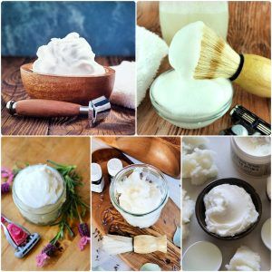
- 25 Homemade DIY Shaving Cream Recipes
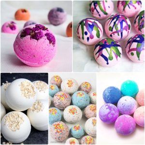
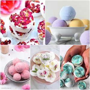
- 30 Homemade DIY Bath Bombs Recipes
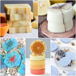
- 80 DIY Homemade Soap Recipes – Make Your Own Soap
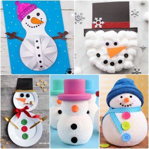
- 30 Easy Snowman Crafts and Ideas for Kids and Adults
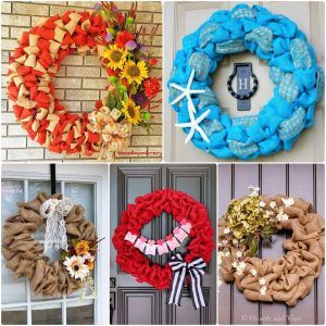
- 25 Easy DIY Burlap Wreath Ideas to Make Your Own
- 30 Resin Crafts and DIY Projects to Make with Epoxy
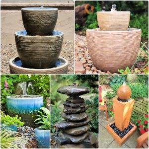
- 25 DIY Water Fountain Ideas to Beautify Your Garden
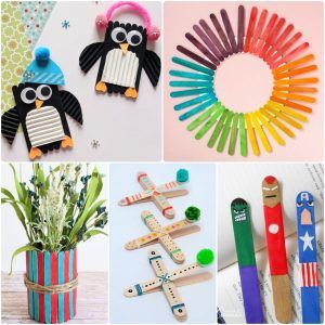
- 30 Easy Popsicle Stick Crafts for All Ages
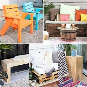
- 30 DIY Patio Furniture Plans and Ideas for Cozy Outdoor
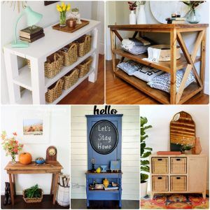
- 30 Free DIY Entry Table Plans and Ideas
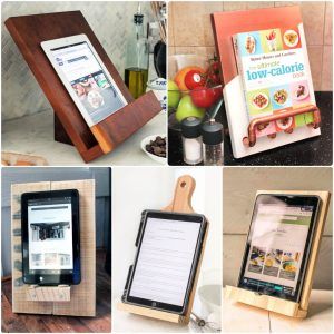
- 15 DIY Tablet Stand and iPad Stand Ideas
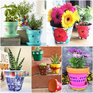
- 20 Clay Pot Painting and Decorating Ideas
- 25 Easy DIY Mail Organizer Ideas to Make
- 35 DIY Cutting Board Ideas and Free Plans
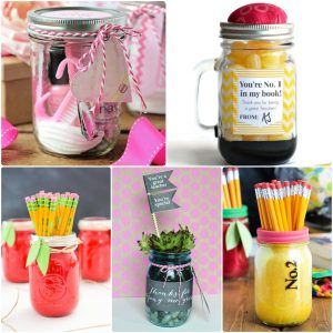
- 20 DIY Mason Jar Teacher Appreciation Gifts
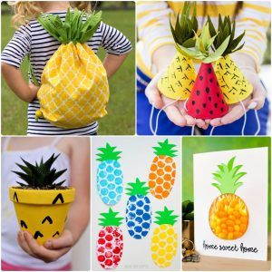
- 30 Fun DIY Pineapple Crafts for Kids
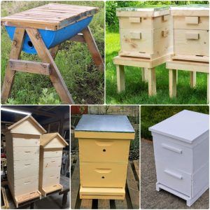
- 25 Free DIY Beehive Plans to Build Your Own Bee Box
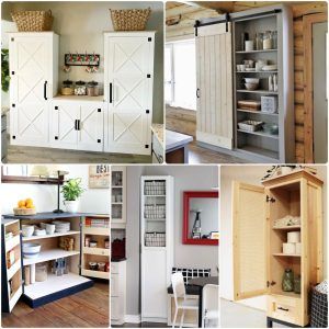
- 25 Free DIY Pantry Cabinet Plans to Build Your Own
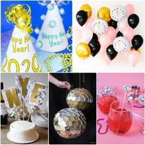
- 30 New Years Eve Party Ideas to Celebrate In Style
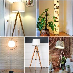
- 30 Creative DIY Floor Lamp Ideas
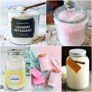
- 40 Homemade Laundry Detergent Recipes You Can DIY
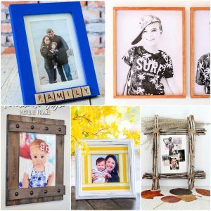
- 30 Homemade DIY Picture Frame Ideas
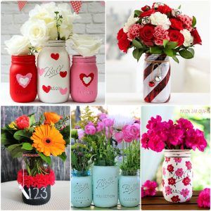
- 30 DIY Mason Jar Vase Ideas for Decoration
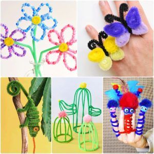
- 30 Easy Pipe Cleaner Crafts and Art Ideas
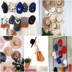
- 25 DIY Hat Rack Ideas – Clever Hat Organizer Ideas
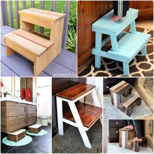
- 20 Free DIY Step Stool Plans
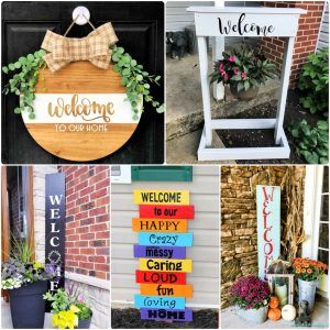
- 20 DIY Welcome Sign Ideas to Make Your Entrance Pop
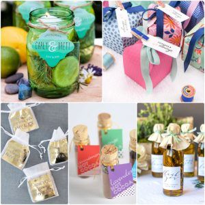
- 30 DIY Wedding Favors That Your Guests Will Love
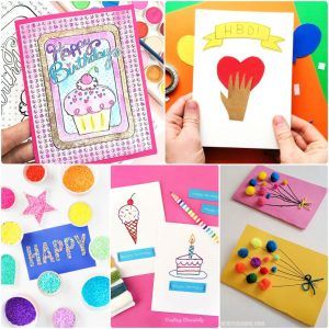
- 20 Homemade DIY Birthday Card Ideas
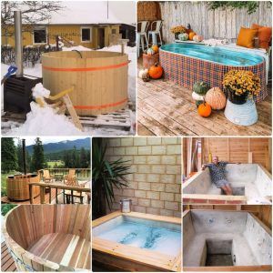
- 20 Homemade DIY Hot Tub Plans and Ideas
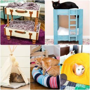
- 25 DIY Cat Bed Ideas You Can Make
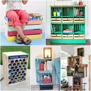
- 30 Unique Wooden Crate Decorating Ideas
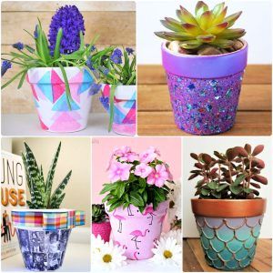
- 30 Cute DIY Flower Pot Ideas You Can Make Yourself
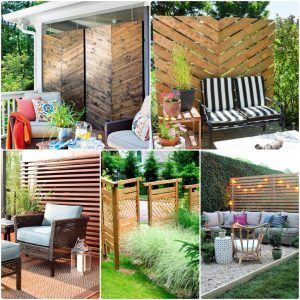
- 25 Cheap DIY Outdoor Privacy Screen Ideas
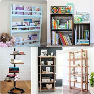
- 40 Free DIY Bookshelf Plans and Ideas You Can Build
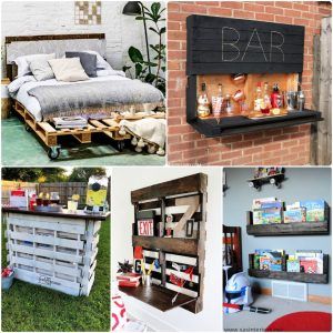
- 40 Cheap DIY Pallet Furniture Ideas and Plans
- 25 Easy DIY Kitchen Backsplash Ideas on a Budget